|
|
PProduct News |
 |
|
|
New Publications: |
|||||||||||||||||||||||||||||||
|
|||||||||||||||||||||||||||||||
NEW PRODUCTS: |
|||||||||||||||||||||||||||||||
|---|---|---|---|---|---|---|---|---|---|---|---|---|---|---|---|---|---|---|---|---|---|---|---|---|---|---|---|---|---|---|---|
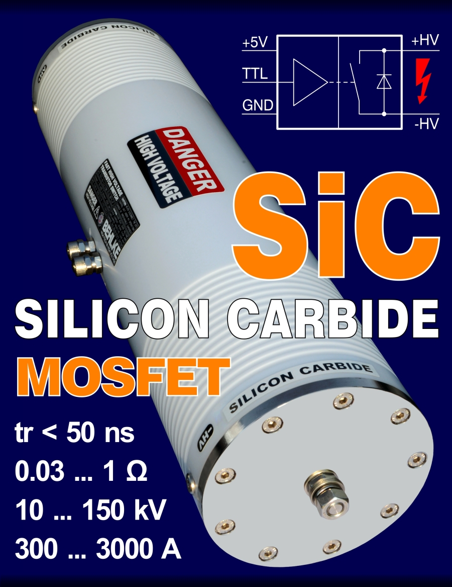
| SiC Silicon Carbide MOSFET switches now available | |||||||||||||||||||||||||||||||
 |
|||||||||||||||||||||||||||||||
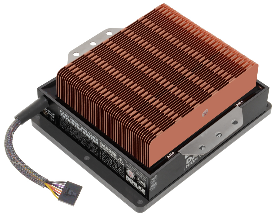
| Cu Double Cooling Fins (Option CF-D) for 100% more power | |||||||||||||||||||||||||||||||
 |
|||||||||||||||||||||||||||||||
|
The image shows a HTS 220-1200-SCR (Fast
Thyristor Switch, 22kV /12 kA) with the new double fin option CF-D. The
double fin option allows 100% more power dissipation compared to the
standard option CF. A further cooling power improvement can be achieved in
combination with option CF-S (fins directly soldered to the power
semiconductors). Both options are applicable to any BEHLKE switch. Please
note, that option CF-D requires forced convection due its reduced cooling
fin spacing. |
|||||||||||||||||||||||||||||||
| Universal cooling boxes for direct liquid cooling (DLC) | |||||||||||||||||||||||||||||||
 |
 |
||||||||||||||||||||||||||||||
 |
|||||||||||||||||||||||||||||||
 |
|||||||||||||||||||||||||||||||
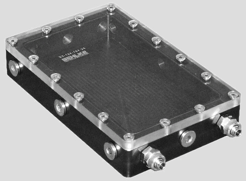
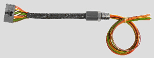
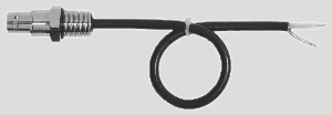
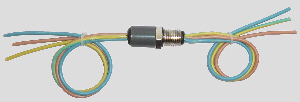
| Fig. 1 DLC Standard Cooling Box, Size B2 | Fig. 2 Electrical Feedthrus for the cooling boxes | ||||||||||||||||||||||||||||||
|
To facilitate the integration of non-DLC components, such as classical power electronic components and periphal circuit boards into a DLC cooling system, BEHLKE has now developed an extensive standard program of pressure proof cooling boxes for universal DLC cooling purposes. The cooling boxes have an inner height of 25 mm (1") and are ideal for printed circuit boards. The inner height can optionally be increased or reduced. The housings have at least 3 threaded holes G1/4 on each side. The G1/4 threads are used for the hose connectors and for the electrical standard feedthrus. Two hose connectors and screw caps are included in the supply. Electrical feedthrus must be ordered separately. The standard feedthru program includes various standard sockets (BNC, BNC-HT, SHV-NIM, LEMO etc.) as well as multiple single ended wires (up to 13 wires per feedthru). Any other customized feedthru can be realized. Board connectors with several hundred pins are possible. The standard housings are made from Delrin and Makrolon. PEEK, PVC and Aluminum are optionally available. Please click here for more information Catalog - Product Group F |
|||||||||||||||||||||||||||||||
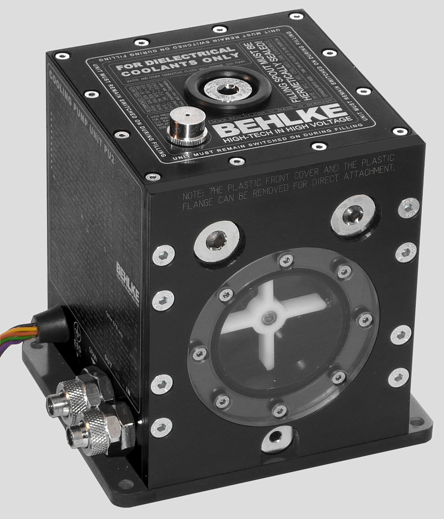
| The new PU2 pump unit for direct liquid cooling (DLC) | |||||||||||||||||||||||||||||||
Please
click here for Data Sheet and Instructions
 Click on the images to enlarge 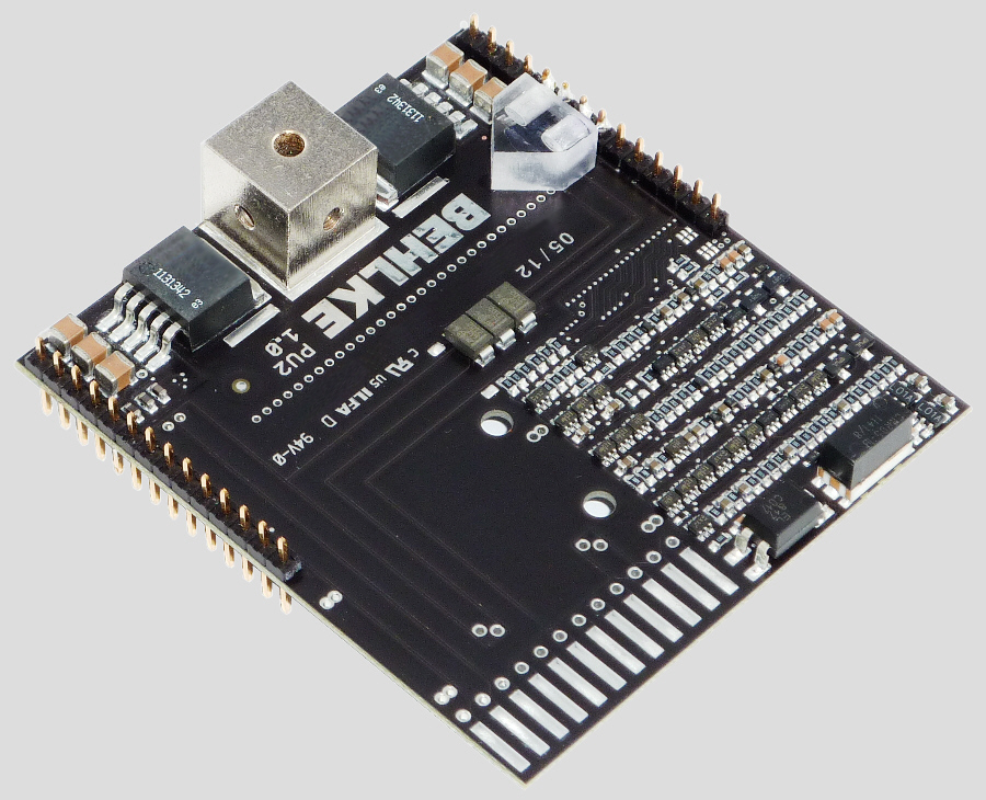
|
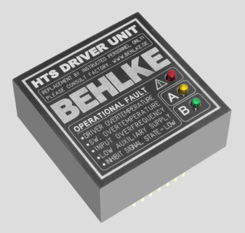
<50�C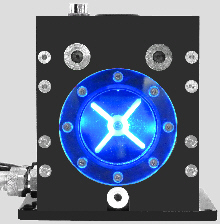 <122�F <122�F |
||||||||||||||||||||||||||||||
|
Blue illumination at normal operation. Blue
flashing if the supply voltage is < 7 Volt or in case of an empty reservoir. |
|||||||||||||||||||||||||||||||
>50�C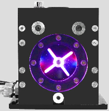 >122�F >122�F |
|||||||||||||||||||||||||||||||
|
Violet illumination if the temperature
exceeds 50�C (122�F), as pre-warning before the over temperature shut-down. |
|||||||||||||||||||||||||||||||
>65�C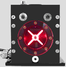 >149�F >149�F |
|||||||||||||||||||||||||||||||
|
Red illumination if there is no coolant flow
detected by the turbine flow sensor (e.g. due to broken or bended tubing). Red flashing if the temperature exceeds 65�C (149 �F). |
|||||||||||||||||||||||||||||||
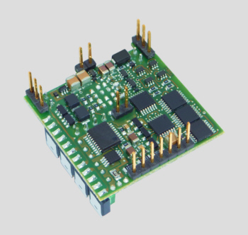
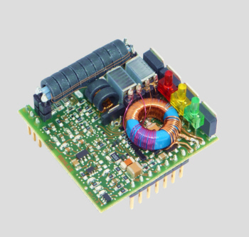
| The internal safety and control electronics of the new PU2 unit. | |||||||||||||||||||||||||||||||
|
The complete board
has three optical sensors for the fill level and the flow rate and two
independent thermo sensors for the temperature protection. The shut-down
of the external power electronics application to be protected is realized by
a (signal) relay with a passive NC contact. The speed of the external
radiator fan as well as the speed of the
pump
motor depends on the neccessary
cooling power and is temperature-dependently controlled. The motor drivers
are liquid cooled. The control electronics is installed
in the coolant reservoir and is completely immersed in the PFPE
liquid. The housing of the PU2 is milled from billet Aluminum and can serve for heat-transfer purposes if attached to a sufficient heat sink. This heatsink can be a heat-conductive machine chassis, a large system housing or any large metal plate. In connection with the option IHE (internal heat exchanger) the heat resistance of the pump housing is reduced to an absolute minimum. The combination of option IHE with a sufficient heat sink can replace the active radiator in low and medium power applications. Above 500 Watt power dissipation the pump unit is usually be combined with an external active radiator or a plate heat exchanger. The pump unit is designed for system integration. It can easely be attached behind the front panel of a 19 inch system housing. In order to align the viewing window with a 19" front panel, the 6 mm (0.24") plastic front cover is replaced by a 3 mm (0.12") plastic spacer (included in supply). Aluminum spacers are available by Behlke if the 19" front panel is to be utilized as heat sink. A front fill port and a front drain for the coolant are provided. For further information please click here. |
|||||||||||||||||||||||||||||||
|
Please
click here for the PU-2 Data Sheet and Instructions Please click here for the BEHLKE DLC demonstration display with PU-2 unit Catalog - Product Group F |
|||||||||||||||||||||||||||||||
| Customized DLC pump units are available on request. Please consult Behlke. | |||||||||||||||||||||||||||||||
 |
|||||||||||||||||||||||||||||||
|
Catalog - Product
Group D
|
|||||||||||||||||||||||||||||||
 |
|||||||||||||||||||||||||||||||